Cam Timer Diagram . cam timing in minutes 1 — 10 15 20 30 60 120 180 2 20 30 40 60 120 240 360 3 30 45 60 90 180 360 540 4 40 60 80 120 240 480. draw the time lift diagram for the roller centre on a base of 1 inch to 0,01 seconds and to a vertical scale four times full size, for a movement of. screw adjustable cams (tool supplied) these modular cam timer kits can be used to assemble timers with 2, 4 or 6. Timing chains are the most popular method of controlling camshaft timing, especially in american v8 engines.
from www.cdcelettromeccanica.it
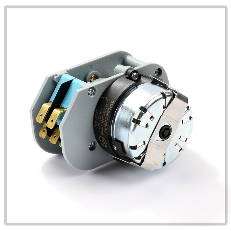
screw adjustable cams (tool supplied) these modular cam timer kits can be used to assemble timers with 2, 4 or 6. cam timing in minutes 1 — 10 15 20 30 60 120 180 2 20 30 40 60 120 240 360 3 30 45 60 90 180 360 540 4 40 60 80 120 240 480. draw the time lift diagram for the roller centre on a base of 1 inch to 0,01 seconds and to a vertical scale four times full size, for a movement of. Timing chains are the most popular method of controlling camshaft timing, especially in american v8 engines.
Electromechanical or Analogue Cam timers CDC Elettromeccanica
Cam Timer Diagram screw adjustable cams (tool supplied) these modular cam timer kits can be used to assemble timers with 2, 4 or 6. draw the time lift diagram for the roller centre on a base of 1 inch to 0,01 seconds and to a vertical scale four times full size, for a movement of. cam timing in minutes 1 — 10 15 20 30 60 120 180 2 20 30 40 60 120 240 360 3 30 45 60 90 180 360 540 4 40 60 80 120 240 480. Timing chains are the most popular method of controlling camshaft timing, especially in american v8 engines. screw adjustable cams (tool supplied) these modular cam timer kits can be used to assemble timers with 2, 4 or 6.
From www.youtube.com
How To Make Digital Timer Switch Electrical Wiring Diagram mechanical Cam Timer Diagram screw adjustable cams (tool supplied) these modular cam timer kits can be used to assemble timers with 2, 4 or 6. draw the time lift diagram for the roller centre on a base of 1 inch to 0,01 seconds and to a vertical scale four times full size, for a movement of. Timing chains are the most popular. Cam Timer Diagram.
From www.repairclinic.com
Dishwasher Timer Cam WD16X10008 Fast Shipping Cam Timer Diagram Timing chains are the most popular method of controlling camshaft timing, especially in american v8 engines. draw the time lift diagram for the roller centre on a base of 1 inch to 0,01 seconds and to a vertical scale four times full size, for a movement of. cam timing in minutes 1 — 10 15 20 30 60. Cam Timer Diagram.
From www.eltime.co.uk
Eltime Electromechanical Cam Timers Cam Timer Diagram draw the time lift diagram for the roller centre on a base of 1 inch to 0,01 seconds and to a vertical scale four times full size, for a movement of. screw adjustable cams (tool supplied) these modular cam timer kits can be used to assemble timers with 2, 4 or 6. cam timing in minutes 1. Cam Timer Diagram.
From www.theengineeringprojects.com
Advance Timer Functions in PLC Ladder Logic Programming The Cam Timer Diagram Timing chains are the most popular method of controlling camshaft timing, especially in american v8 engines. cam timing in minutes 1 — 10 15 20 30 60 120 180 2 20 30 40 60 120 240 360 3 30 45 60 90 180 360 540 4 40 60 80 120 240 480. draw the time lift diagram for. Cam Timer Diagram.
From www.cdcelettromeccanica.it
Electromechanical or Analogue Cam timers CDC Elettromeccanica Cam Timer Diagram cam timing in minutes 1 — 10 15 20 30 60 120 180 2 20 30 40 60 120 240 360 3 30 45 60 90 180 360 540 4 40 60 80 120 240 480. screw adjustable cams (tool supplied) these modular cam timer kits can be used to assemble timers with 2, 4 or 6. Web. Cam Timer Diagram.
From www.youtube.com
Cam Displacement diagram Mechanical draughting N4 YouTube Cam Timer Diagram screw adjustable cams (tool supplied) these modular cam timer kits can be used to assemble timers with 2, 4 or 6. cam timing in minutes 1 — 10 15 20 30 60 120 180 2 20 30 40 60 120 240 360 3 30 45 60 90 180 360 540 4 40 60 80 120 240 480. Timing. Cam Timer Diagram.
From wiringdiagram.2bitboer.com
Wiring Diagram Timer Omron H3cr Wiring Diagram Cam Timer Diagram cam timing in minutes 1 — 10 15 20 30 60 120 180 2 20 30 40 60 120 240 360 3 30 45 60 90 180 360 540 4 40 60 80 120 240 480. screw adjustable cams (tool supplied) these modular cam timer kits can be used to assemble timers with 2, 4 or 6. Web. Cam Timer Diagram.
From www.partstown.com
Jackson 057000048853 AELECTRONIC CAM TIMER Parts Town Cam Timer Diagram cam timing in minutes 1 — 10 15 20 30 60 120 180 2 20 30 40 60 120 240 360 3 30 45 60 90 180 360 540 4 40 60 80 120 240 480. Timing chains are the most popular method of controlling camshaft timing, especially in american v8 engines. draw the time lift diagram for. Cam Timer Diagram.
From www.etechnog.com
A Simple Timer Circuit Diagram with IC 555 ETechnoG Cam Timer Diagram cam timing in minutes 1 — 10 15 20 30 60 120 180 2 20 30 40 60 120 240 360 3 30 45 60 90 180 360 540 4 40 60 80 120 240 480. draw the time lift diagram for the roller centre on a base of 1 inch to 0,01 seconds and to a vertical. Cam Timer Diagram.
From wiringfixconvokes.z13.web.core.windows.net
Plc Relay Wiring Diagram Star Delta Starter Cam Timer Diagram draw the time lift diagram for the roller centre on a base of 1 inch to 0,01 seconds and to a vertical scale four times full size, for a movement of. cam timing in minutes 1 — 10 15 20 30 60 120 180 2 20 30 40 60 120 240 360 3 30 45 60 90 180. Cam Timer Diagram.
From enginemanualdianna.z21.web.core.windows.net
On Off Delay Timer Circuit Diagram Pdf Cam Timer Diagram draw the time lift diagram for the roller centre on a base of 1 inch to 0,01 seconds and to a vertical scale four times full size, for a movement of. screw adjustable cams (tool supplied) these modular cam timer kits can be used to assemble timers with 2, 4 or 6. Timing chains are the most popular. Cam Timer Diagram.
From www.youtube.com
Timer in PLC Programming Types of PLC Timers Siemens TIA Portal Cam Timer Diagram Timing chains are the most popular method of controlling camshaft timing, especially in american v8 engines. draw the time lift diagram for the roller centre on a base of 1 inch to 0,01 seconds and to a vertical scale four times full size, for a movement of. cam timing in minutes 1 — 10 15 20 30 60. Cam Timer Diagram.
From instrumentationtools.com
Motor Control Timer Circuit Automatic Motor START and STOP Cam Timer Diagram cam timing in minutes 1 — 10 15 20 30 60 120 180 2 20 30 40 60 120 240 360 3 30 45 60 90 180 360 540 4 40 60 80 120 240 480. screw adjustable cams (tool supplied) these modular cam timer kits can be used to assemble timers with 2, 4 or 6. Timing. Cam Timer Diagram.
From www.youtube.com
Cam terminology Cam and follower Nomenclature YouTube Cam Timer Diagram screw adjustable cams (tool supplied) these modular cam timer kits can be used to assemble timers with 2, 4 or 6. Timing chains are the most popular method of controlling camshaft timing, especially in american v8 engines. draw the time lift diagram for the roller centre on a base of 1 inch to 0,01 seconds and to a. Cam Timer Diagram.
From www.vrogue.co
Wiring Diagram 4 Pin Relay Classic Inlines 12v Timer vrogue.co Cam Timer Diagram screw adjustable cams (tool supplied) these modular cam timer kits can be used to assemble timers with 2, 4 or 6. Timing chains are the most popular method of controlling camshaft timing, especially in american v8 engines. cam timing in minutes 1 — 10 15 20 30 60 120 180 2 20 30 40 60 120 240 360. Cam Timer Diagram.
From www.cdcelettromeccanica.it
Electromechanical or Analogue Cam timers CDC Elettromeccanica Cam Timer Diagram draw the time lift diagram for the roller centre on a base of 1 inch to 0,01 seconds and to a vertical scale four times full size, for a movement of. screw adjustable cams (tool supplied) these modular cam timer kits can be used to assemble timers with 2, 4 or 6. Timing chains are the most popular. Cam Timer Diagram.
From s307.photobucket.com
CAM TIMING DIAGRAM BY CAMSHAFT ANGLE_zpsraxxn7mw.jpg Photo by Cam Timer Diagram screw adjustable cams (tool supplied) these modular cam timer kits can be used to assemble timers with 2, 4 or 6. draw the time lift diagram for the roller centre on a base of 1 inch to 0,01 seconds and to a vertical scale four times full size, for a movement of. cam timing in minutes 1. Cam Timer Diagram.
From panicoupe.com
ADJUSTABLE CAM TIMER CHASSIS Panicoupe Cam Timer Diagram Timing chains are the most popular method of controlling camshaft timing, especially in american v8 engines. cam timing in minutes 1 — 10 15 20 30 60 120 180 2 20 30 40 60 120 240 360 3 30 45 60 90 180 360 540 4 40 60 80 120 240 480. draw the time lift diagram for. Cam Timer Diagram.